TM-9-2350-311-20-2 - Page 515 of 828
TM 9–2350–311–20–2
Change 2
9–13
2
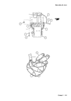
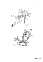
Connect five electrical leads at quick disconnects (9).
NOTE
Do not tighten cap screws until adjustment is completed.
3
Install electrical contact arm (5) on hull using four cap screws (6) and four new lockwashers (7). New shims
(8) should be used as necessary to secure correct clearance (para 9–3f.).
4
Using two cap screws (3) and two new lockwashers (4), attach free end of two ground straps (1) and ground
wire (2) from harness to hull.
5
Adjust electrical contact arms (5) to segment board (para 9–3f.).
9
100
GND
100
GND
41
42
43
L1
L2
8
7
6
5
4
3
2
1
1
Back to Top


