TM-9-2350-311-34-1 - Page 78 of 352
TM 9-2350-311 -34-1
4-5 CRANKSHAFT
VIBRATION DAMPER
This task covers:
a. Removal
b. Disassembly
c. Inspection
d. Assembly
e. Installation
Tools
Torque wrench (item 28, Appx C)
General mechanic’s tool kit (item 14, Appx C)
Hammer (item 13, Appx C)
Torque wrench (item 26, Appx C)
Split cone (item 77, Appx F)
Torque wrench (item 27, Appx C)
a. Removal
1
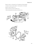
Loosen bolt (1) approximately 0.125 in. (3.2 mm).
2 Strike bolt (1) with hammer to loosen spilt cone (2).
3
Remove bolt (1), spacer (3), split cone (2), and hub and damper assembly (4). Discard spiit cone.
b. Disassembly
1
Remove six bolts (5) and six washers (6).
2 Separate hub (7) and damper (8).
c. Inspection
Inspect damper (8), hub (7), and spacer (3). Replace damaged items as required.
d. Assembly
Install six washers (6) and six bolts (5) to hub (7) and damper (8). Torque bolts to 60-70 lb-ft (81-95 N•m).
e.
Installation
1 Install damper and hub assembly (4), new split cone (2), spacer (3), and bolt (1). Torque bolt to 180 Ib-ft (244
N•m),
2 Strike bolt (1) with hammer.
3 Torque bolt (1) to 300 Ib-ft (407 N•M). Strike bolt with hammer again.
4 Torque bolt (1) to 300-330 lb-ft (407-447 N•m).
4-22
Back to Top


