TM-9-2350-311-34-1 - Page 80 of 352
TM 9-2350-311-34-1
4-6 TRANSMISSION TRUNNION REPLACEMENT CAPS — CONTINUED
a. Replacement Trunnion Cap Preparation
1
2
3
4
5
6
7
8
9
10
11
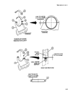
Locate and mark centerline of two support bolt holes (1) on front and rear of support (2).
Locate and mark center of replacement trunnion cap (3) on front and rear vertical face of cap.
With powerplant installed and transmission positioned in supports, place replacement trunnion cap (3) with
insert (4) over support (2). Aline center mark on cap with hole center marks on support.
Measure pretorque clearance between cap (3) and support (2) at forward and rear edges. Clearance should be
0.005 to 0.007 in. (0.13 to 0.18 mm).
If clearance is less than 0.005 in. (0.13 mm), machine trunnion cap mating surfaces to obtain required
clearance. If clearance is greater than 0.007 in. (0. 18 mm), use shims (5) as required to reduce gap.
Remove replacement trunnion cap (3) with insert (4) and leave shims (5) (as required) in place on support (2).
Install two socket head setscrews (6) in two support bolt holes (1).
NOTE
Screw must protrude 0.005 to 0.010 in. (0.13 to 0.25 mm) above support face or shim
surface, if shims are used.
Apply marking dye to mating surface of replacement trunnion cap (3).
Reposition replacement trunnion cap (3) and strike top of cap with hammer. Socket head setscrews (6) will
mark hole location outlines in marking dye.
Remove replacement trunnion cap (3) and socket head setscrews (6). Caps must be immediately marked “LF”
or “RF” on forward surface to indicate if cap was removed from the left front or the right front (viewed from
driver’s compartment facing forward).
Drill two 0.531 in. (13.49 mm) holes from bottom of trunnion cap (3) using outline of setscrews as location
points. Holes must be free of burrs.
4-24
Back to Top


