TM-9-2520-234-35 - Page 179 of 323
*C2
*C2
*C2
PAR
177-181
REVERSE PLANETARY AND SUPPORT REBUIL D
CHAP
5,
SEC
XXII I
Section XXIII. REVERSE-RANGE PLANETARY AND SUPPORT ASSEMBLY — REBUILD
177. DESCRIPTIO N
Refer to par. 14 for description of the re-
verse-range planetary and support assembly.
178. DISASSEMBLY (fig. 377, fold-out 6)
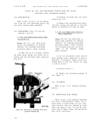
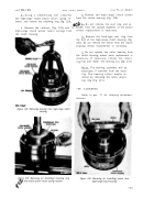
a . Using a press, remove the reverse-
range planetary carrier assembly from it s
support (fig. 212).
b . Remove the retaining ring retaining
the bearing in the carrier support (fig. 212).
c . Using a press, remove the bearin g
from the carrier support (fig. 212).
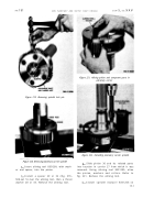
d . Using a hammer and punch, remove
six lock pins retaining the planetary carrier
spindles (fig. 213).
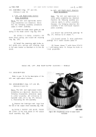
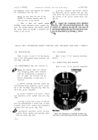
e . Position the reverse-range planetary
carrier assembly in a press. Using a suitable
pressing tool, remove six carrier spindle s
(fig. 214). Remove the pinions 14 (fig. 377,
fold-out 6), thrust washers 8 and 15, spacers
9, 11 and 13, and roller bearings 10 and 12.
Figure 212. Removing reverse-range planetary carrier
assembly
179. CLEANIN G
Refer to par. 71 for cleaning recommen-
dations.
180. INSPECTION AND REPAIR
Refer to par. 72 for general inspection
and repair recommendations. Repair and re-
build points of measurement for fits, clear-
ances and wear limits are indicated by small,
lower case letters in fig. 377, fold-out 6. Re-
fer to par. 240 for wear limits information.
181. ASSEMBLY (fig. 377, fold-out 6)
Note . Chill spindles 7 in dry ice for
approximately one hour, prior to in-
stallation.
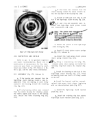
a . Place reverse-range planetary car -
rier 17, hub side down, in a press.
Figure 213. Removing (or installing) spindle lock pins
14 7
Back to Top


