TM-9-2520-234-35 - Page 182 of 323
*C2
*C2
CHAP
5,
SEC
XX V
184. CLEANIN G
Refer to par.
dations.
LOW PLANETARY AN D
71 for cleaning recommen-
185. INSPECTION AND REPAIR
Refer to par. 72 for general inspection
and repair recommendations. Repair and re-
build points of measurement for fits, clear-
ances and wear limits are indicated by small,
lower case letters in fig. 376, fold-out 5. Re-
fer to par. 239 for wear limits information.
186. ASSEMBLY (fig. 376, fold-out 5)
a.
in low-
ing 55.
Install expander 54 and ring seal 53
and reverse-range clutch piston hous-
OUTPUT SHAFT REBUIL D
PAR
184-191
b . Install expander 51 and ring seal 52
onto low-range clutch piston 50.
c . Install low-range clutch piston 50 into
housing 55.
d . Install eighteen piston return springs
49 onto piston 50.
e . Install piston return spring retainer 48.
f.
Position
assembly
in
a
press
and
using a compressing tool, compress pisto n
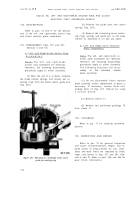
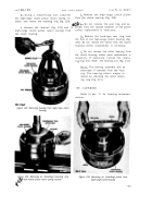
springs and install retaining ring (fig. 218).
g . Install reverse-range clutch piston 60
(fig. 376, fold-out 5) and related parts in hous-
ing 55, in the same manner, as described for
low-range in a through f , above.
—
Section XXV. LOW-RANGE PLANETARY AND OUTPUT SHAFT — REBUILD
187. DESCRIPTIO N
Refer to par. 13 for description of the
low-range planetary and output shaft assembly.
188. DISASSEMBLY (fig. 376, fold-out 5)
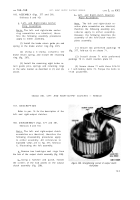
a . Using a hammer and punch, remove
the four planetary spindle lock pins retaining
the planetary spindles (fig. 219).
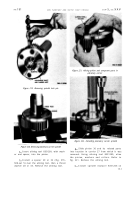
b . Using a press, and a suitable press
tool, remove four planetary carrier spindles
(fig. 220).
c . Remove planetary pinion 30 (fig. 376,
fold-out 5), spacers 32 and 29, thrust washers
33 and 28, and rollers 31.
d . Remove the three remaining planetary
pinions 30 and related parts.
189. CLEANIN G
Refer to par. 71 for cleaning recommen-
dations.
15 0
190. INSPECTION AND REPAIR
Refer to par. 72 for general inspection
and repair recommendations. Repair and re-
build points of measurement for fits, clear-
ances and wear limits are indicated by small,
lower case letters in fig. 376, fold-out 5. Re-
fer to par. 239 for wear limits information.
191.
in a
ASSEMBLY (fig. 376, fold-out 5)
Note . Chill spindles 34 in dry ice for
approximately one hour prior to in-
stallation.
a . Place low-range shaft and carrier 27
press .
b . Grease the inside diameter of plane-
tary carrier pinion assembly 30.
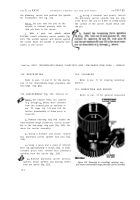
c . Insert 20 spindle rollers into the pin-
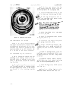
ion bore. Refer to fig. 215.
d . Place a thrust washer and spacer on
alining tool 8351209. Refer to fig. 215.
Back to Top


