TM-9-2520-234-35 - Page 189 of 323
*C2
PAR
202-20 3
TRANSMISSION HOUSING REBUIL D
CHAP
5,
SEC
XXVII I
Section XXVIII. TRANSMISSION HOUSING — REBUILD
202. DESCRIPTIO N
The transmission main housing is a cast
aluminum alloy housing. It houses and sup-
ports the range gearing, range clutches, left-
steer planetary carrier, brake, steer clutch
and output clutch assemblies. The main hous-
ing also serves as the oil sump for the trans-
mission .
203. DISASSEMBLY (fig. 375, fold-out 4)
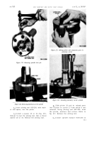
a . Remove two hook-type seal rings from
the hub of the diaphragm (fig. 232).
b . Remove the thrust washer (fig. 232).
c . Remove two preformed packings from
the transmission housing (fig. 232).
Figure 232.
Removing hook-type seal ring from hub of
diaphragm assembly
d . Remove retaining ring that retain s
bearing
(fig. 232).
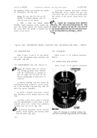
e . If necessary to remove the diaphragm
assembly, use a 9/16-inch wrench to remove
four self-locking bolts retaining diaphragm.
Position housing in a press, and press out the
diaphragm. Refer to fig. 233.
f . If the diaphragm assembly was re -
moved, remove the diaphragm clamp plate.
Refer to fig. 232.
g . Remove the gage rod cap from the oil
filler assembly. Refer to fig. 233.
h . Using a 9/16-inch wrench, remov e
four bolts and lock washers from the oil filler
tube assembly .
Remove the oil filler tube
assembly. Refer to fig. 233.
i . Using a 9/16-inch wrench, remove six
cap screws (two different lengths) and lock
washers that retain the accumulator body. Re-
move the accumulator body. Refer to fig. 233.
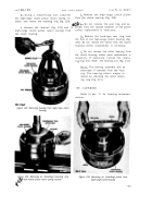
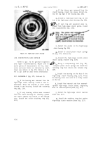
Figure 233. Transmission main housing
15 7
Back to Top


