TM-9-2520-234-35 - Page 197 of 323
PAR
227,
STEPS
7-1 0
ASSEMBL Y
CHAP
5,
SEC
XXXII I
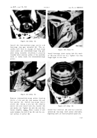
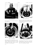
Figure 246 (Step 7)
Install oil collector (A) into transmission hous-
ing (B).
Figure 247 (Step 8)
Install intermediate-range clutch anchor (A).
Install anchor bolt (B). Install washer (C) and
nut (D). Tighten nut only finger-tight.
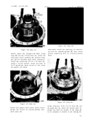
Figure 248 (Step 9)
Install two internal- (A) and two external- (B)
splined intermediate-range clutch plates, be-
ginning with an internal-splined plate.
Figure 249 (Step 10)
Install intermediate-range ring gear assem-
bly (A). Install an internal- (B), an external-
(C) and the remaining internal-splined (D),
intermediate-range clutch plates.
16 5
Back to Top

