TM-9-2520-234-35 - Page 204 of 323
*C2
CHAP
5,
SEC
XXXII I
ASSEMBL Y
PAR
227,
STEPS
35-3 8
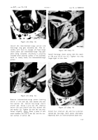
Figure 274 (Step 35)
Install brake anchor assembly (A). Instal l
sixteen 7/16- 14x 7-1/2 bolts (B) and one 7/16-
14 x 7 bolt (D). Remove guide bolt (C) and
install remaining 7/16- 14 x 7 bolt (D). Using
a 5/8-inch wrench, torque the eighteen bolts
to 42-50 pound-feet.
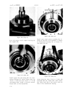
Figure 276 (Step 37)
Raise the transmission housing (A) and install
3/4-16
self-locking
bolt
(B)
and
lock
plate
(C)
into the end of the steer planetary carrier and
shaft assembly. Tighten bolt only finger-tight
at this time.
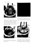
Figure 275 (Step 36)
Using hoist and sling (A), install the geared
steer planetary carrier and shaft assembly
(B). Remove the sling and tap the assembly
down while rotating it.
17 2
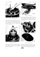
Figure 277 (Step 38)
Position the transmission housing on its bot-
tom. Install 10 external- (A) and 10 internal-
splined (B) left-brake plates alternately, be-
ginning with an external-splined plate (A).
Back to Top


