TM-9-2520-234-35 - Page 212 of 323
CHAP
5,
SEC
XXXII I
ASSEMBL Y
PAR 227, STEPS
67-7 0
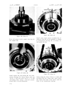
Figure 306 (Step 67)
Install snap ring (A). Install output oil pump
drive gear (B), flat side out.
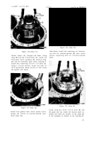
Figure 307 (Step 68)
Install gasket (A) on left-output support as-
sembly (B). Install support assembly.
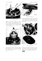
Figure 308 (Step 69)
Install lifting bracket (A), three 7/16-14 x
1-3/4 (B) and ten 7/16-14 x 1-1/2 bolts (C)
with lock washers. Using a 5/8-inch wrench,
torque bolts to 42-50 pound-feet.
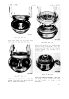
Figure 309 (Step 70)
Install left-output coupling (A). Install lock
plate (B) and 3/4-16 x 2-3/4 bolt (C), finger
tight.
18 0
Back to Top


