TM-9-2520-234-35 - Page 216 of 323
CHAP
5,
SEC
XXXII I
ASSEMBL Y
PAR
227,
STEPS
83-8 6
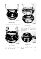
Figure 322 (Step 83)
Figure 324 (Step 85)
Install main control valve body assembly gas-
ket (A) and body assembly (B).
Figure 323 (Step 84)
Install six 5/16-18 x 2-1/2 (A) and twenty-two
5/16-18
x
2-1/4-inch
bolts
(B)
with
lock
wash-
ers to retain main control valve body assembly
(C). Using a 1/2-inch wrench, torque bolts
to 13-16 pound-feet.
Install lockup shift and pressure regulator
valve body oil transfer plate gasket (A) and
plate (B).
Figure 325 (Step 86)
Install lockup shift and pressure regulator
valve body assembly gasket (A) and body as-
sembly (B).
18 4
Back to Top


