TM-9-2520-234-35 - Page 222 of 323
*C2
CHAP
5,
SEC
XXXII I
ASSEMBL Y
PAR
228,
STEPS
19-2 2
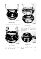
Figure 346 (Step 19)
Position torque converter assembly (A) on the
assembly table, leveling it on wooden blocks
(B). Install two 3/8-24 headless guide bolts
(C) in assembly (A). Using sling (D), lower
input transfer gear housing assembly (E) onto
converter assembly (A). After installation,
level housing assembly (E) with wooden blocks.
Figure 347 (Step 20)
Remove headless guide bolts. Install torque
converter bearing cover (A) and gasket (B).
19 0
Figure 348 (Step 21)
Install eight 3/8-24 x 2-1/4 bolts (A) and lock
washers (B) to retain converter bearing cover
(C). Using a 9/16-inch wrench, torque bolts
to 33-40 pound-feet.
Figure 349 (Step 22)
Install transfer idler cluster gear spindle lock
strap (A), lock strip (B) and two 3/8-16 x 1
bolts (C). Using a 9/16-inch wrench, torque
bolts to 26-32 pound-feet. Bend corners of
strip (B) against bolt heads.
Back to Top


