TM-9-2520-234-35 - Page 225 of 323
*C2
PAR
229,
STEPS
3- 6
ASSEMBL Y
CHAP
5,
SEC
XXXII I
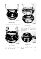
Figure 358 (Step 3)
Position assembled housing (A) on stand (B).
Using sling (C),install output drive planetary
ring gear (D) .
Figure 359 (Step 4)
Install lock plate (A) and secure with two lock
strips (B) and four 5/8-18 x 2-1/2 bolts (C).
Using a 15/16-inch wrench, torque the bolts
to 134-160 pound-feet. Bend a tab of loc k
strips (B) against the head of each bolt (C).
Figure 360 (Step 5)
Using sling (A) and a headless 7/8-14 guide
bolt (B), install saddle assembly (C) onto
planetary carrier assembly (D), alining index
marks (E).
Figure 361 (Step 6)
Remove headless guide bolt.
ers (A) and 24 bolts (B). Do
at this time.
19 3
Back to Top


