TM-9-2520-234-35 - Page 218 of 323
*C2
CHAP
5,
SE C
XXXlll
ASSEMBL Y
PAR
228,
STEPS
3- 6
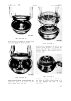
Figure 330 (Step 3)
Install idler cluster gear spindle assembly (A).
Figure 331 (Step 4)
Install input transfer cluster gear and bearing
assembly (A) and spacer (B), alining parts
with the spindle bore in housing (C).
18 6
Figure 332 (Step 5)
Install O-ring seals (A) onto cluster gea r
spindle (B). Install spindle (B) with seals (A)
into housing (C), and cluster gear and bear-
ing assembly. Be sure that oil hole (D) in
spindle is up.
Figure 333 (Step 6)
Install lock strap (A), lock strip (B) and two
3/8-16 x 1 bolts (C). Using a 9/16-inch wrench,
torque bolts to 26-32 pound-feet. Bend cor-
ners of strip (B) against the bolt heads.
Back to Top


