TM-9-2520-234-35 - Page 224 of 323
*C2
CHAP
5,
SEC
XXXII I
ASSEMBL Y
PAR
228-22 9
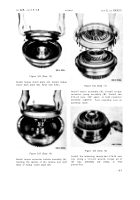
Figure 354 (Step 27)
Install engine coupling shaft (A). Install two
7/16-14 x 5-1/4 (B), four 7/16-14 x 6 (C) and
four 7/16-14 x 1-1/2 converter housing-to -
input transfer housing bolts (D) with lock
washers .
Using a 5/8-inch wrench, torque
bolts to 42-50 pound-feet.
Figure 355 (Step 28)
Remove brake inspection covers (A) whic h
were temporarily installed. Refer to sec .
XXXIV, par. 234 for a final brake adjustment.
Install gaskets (B) and covers (A). Secure
covers with twelve 3/8-16 x 1-1/8 bolts (C)
with lock washers. Using a 9/16-inch wrench,
torque bolts to 26-32 pound-feet.
229. ASSEMBLY STEPS – LEFT- AND
RIGHT-OUTPUT DRIVE ASSEMBLIES
Figure 356 (Step 1)
Install gasket (A) and sleeve (B) onto output
shaft assembly (C). Using sling (D), install
output drive housing (E).
Figure 357 (Step 2)
Install eight 7/16-20 x 1-1/4 bolts (A). Using
a
5/8-inch
wrench,
torque
bolts
to
50-60
pound-feet .
Install lock wire (B) through
bolts (A).
19 2
Back to Top


