TM-9-2520-234-35 - Page 223 of 323
*C2
PAR
228,
STEPS
23-2 6
ASSEMBL Y
CHAP
5,
SEC
XXXII I
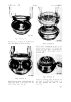
Figure 350 (Step 23)
Install input oil pump assembly (A) and gasket
(B) into transfer housing (C).
Figure 351 (Step 24)
Install six 3/8-16 x 1-1/2 (A) and five 3/8-16
x 3-3/4 bolts (B) with lock washers to retain
input oil pump assembly (C). Using a 9/16-
inch wrench, torque bolts to 26-32 pound-feet.
Figure 352 (Step 25)
Install gasket (A) on input transfer housing
assembly (B). Using sling (C) install housing
assembly (B) onto transmission assembly (D).
Figure 353 (Step 26)
Install sixteen 7/16-14 x 1-1/2 converter hous-
ing-to-input transfer housing assembly bolts
(A) with lock washers (B). Using a 5/8-inch
wrench, torque bolts to 42-50 pound-feet.
19 1
Back to Top


