TM-9-2520-234-35 - Page 221 of 323
PAR
228,
STEPS
15-1 8
ASSEMBL Y
CHAP
5,
SEC
XXXII I
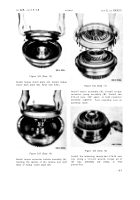
Figure 342 (Step 15)
Install lockup clutch plate (A). Install lockup
clutch back plate (B). Aline bolt holes.
Figure 343 (Step 16)
Install torque converter turbine assembly (A),
meshing the splines of the turbine hub with
those of lockup clutch plate (B).
Figure 344 (Step 17)
Install stator assembly (A). Install torque
converter pump assembly (B). Install two
5/16-24 nuts, 180° apart, to hold converter
assembly together.
Turn assembly over o n
assembly table.
Figure 345 (Step 18)
Install the remaining twenty-two 5/16-24 nuts
(A). Using a 1/2-inch wrench, torque all of
the
nuts,
alternately
and
evenly,
to
19-23
pound-feet.
18 9
Back to Top


