TM-9-2520-234-35 - Page 217 of 323
PAR
227-22 8
ASSEMBL Y
CHAP
5,
SEC
XXXII I
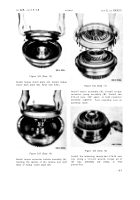
Figure 326 (Step 87)
Install eighteen 5/16-18 x 3-1/4 bolts (A) with
flat washers to retain lockup shift and pres-
sure regulator valve body assembly (B). Us-
ing a 1/2-inch wrench, torque bolts to 13-16
pound-feet. Install main oil screen assembly
(C). Be sure that oil seal ring (D) is in place.
Figure 327 (Step 88)
Install three 3/8-24 x 1-1/8 bolts (A) with lock
washers to retain main oil screen assembly
(B). Using a 9/16-inch wrench, torque bolts
to 33-40 pound-feet. For cleanliness, tempo-
rarily install two 1-inch pipe plugs (C).
228. ASSEMBLY STEPS –
INPUT TRANSFER ASSEMBLY
Figure 328 (Step 1)
Install bearing assembly (A) in input transfer
housing
(B).
Install
input
oil
pump
drive
gear (C).
Figure 329 (Step 2)
Install input transfer idler cluster gear and
bearing assembly (A), alining it with spindle
bore (B) in housing (C).
18 5
Back to Top


