TM-9-2520-234-35 - Page 207 of 323
*C2
PAR
227,
STEPS
47-5 0
ASSEMBL Y
CHAP
5,
SEC
XXXII I
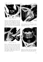
Figure 286 (Step 47)
Install two 1/2-13 x 1-3/4 bolts (A) and lock
washers (B). Install the remaining 7/16-1 4
x 1-1/2 bolts (C) and lock washers (D). Tighten
all split line bolts. Torque 7/16, 1/2, an d
5/8 bolts to 42-50, 67-80 and 117-140 pound-
feet, respectively.
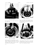
Figure 288 (Step 49)
Install the remaining thirteen 3/8-16 x 1-3/8
bolts (A) with lock washers (B) and four 3/8-16
x 2-1/2 bolts (C) with lock washers (D). Using
a 9/16-inch wrench, torque all of the bolts to
26-32 pound-feet.
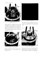
Figure 287 (Step 48)
Install gasket (A) on brake coolant oil pump
and manifold assembly (B). Note . Be sur e
that valves (C) remain in proper position dur-
ing installation of assembly (B). Install two
3/8-16 x 1-3/8 mounting bolts with lock wash-
ers to initially retain the pump and manifold
assembly .
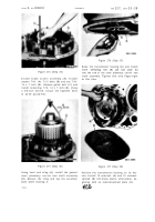
Figure 289 (Step 50)
Using a 15/16-inch socket wrench, tighte n
the intermediate- and low-range clutch hous-
ing nuts (A) to 134-160 pound-feet torque.
Using a 9/16-inch wrench, tighten the inter-
mediate- ,
and low- and reverse-range clutch
piston housing bolts (B) to 26-32 pound-feet
torque.
17 5
Back to Top


