TM-9-2520-234-35 - Page 201 of 323
PAR
227,
STEPS
23-2 6
ASSEMBL Y
CHAP
5,
SEC
XXXII I
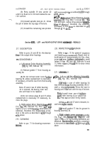
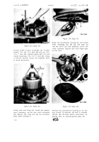
Figure 262 (Step 23)
Install thrust washer (A) and sleeve (B) onto
low-range carrier and shaft assembly (C) .
Alternately install three external- (D) and
three
internal-splined
(E),
reverse-range
clutch plates, beginning with an external -
splined plate (D).
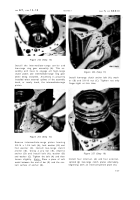
Figure 263 (Step 24)
Install reverse-range ring gear assembly (A),
chamfered side up. Install an external-splined
(B) and the remaining internal-splined (C),
reverse-range clutch plate. Aline the tangs
of plates (B) and center the plates carefully.
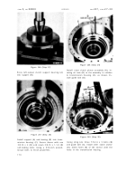
Figure 264 (Step 25)
Using sling (A) and two 7/16-14 bolts (B) and
nuts (C), install reverse-range carrier an d
support housing assembly (D).
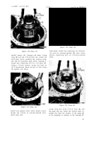
Figure 265 (Step 26)
Install two 3/8-16 screws (A) that retai n
reverse-range carrier support housing (B) .
Tighten screws evenly until housing (B) is
firmly seated.
16 9
Back to Top


