TM-9-2520-234-35 - Page 209 of 323
PAR
227
STEPS
55-5 8
ASSEMBL Y
CHAP
5,
SEC
XXXll l
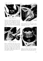
Figure 294 (Step 55)
Install twenty-seven 7/16-14 x 1-1/2 (A), and
four 7/16-14 x 7-1/2 (B) bolts with lock wash-
ers. Install lifting bracket (C) and three 7/16-
14 x 1-3/4 bolts (D) with lock washers. Us-
ing a 5/8-inch wrench, torque all bolts to
42-50 pound-feet.
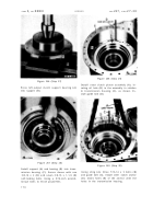
Figure 295 (Step 56)
Install accumulator body (A) and gasket (B).
Secure body with four 3/8-16 x 1-1/2-inch (C)
and two 3/8-16 x 2-1/2 bolts (D) and six wash-
ers (E). Using a 9/16-inch wrench, torque
all bolts to 26-32 pound-feet.
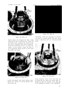
Figure 296 (Step 57)
Make a preliminary brake assembly adjust-
ment at this time.
Insert gage (A) between
rotating cam and first plate. Turn brake ad-
justing nut (B) clockwise, until brake plate
clearance equals the gage thickness. Adjust
the left-brake assembly clearance in the same
manner .
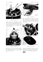
Figure 297 (Step 58)
Using wrench (A), apply the right brake. Us-
ing a 1-inch wrench, tighten right-outpu t
coupling bolt (B) to 337-385 pound-feet torque.
17 7
Back to Top


