TM-9-2520-246-34-1 - Page 222 of 418
TM 9-2520-246-34-1
b.
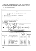
Countershaft Assembly.
FRAME 1
NOTE
Readings must be within limits given in table 2-41. If
readings are not within given limits, throw away part
and get a new one.
1.
Measure high range gear bore (1) and high range gear keyway width (2).
2.
Measure countershaft diameter (3) in two places and two countershaft keyway
widths (4).
3.
Measure two key widths (5).
4.
Measure low range gear bore (6) and low range gear keyway width (7).
GO TO FRAME 2
Index Number
1
2
3
4
5
6
7
2-202
Table 2-41. Countershaft Assembly Wear Limits
Item/Point of Measurement
High range gear bore
High range gear keyway width
Countershaft diameter
Countershaft keyway width
Key width
Low range gear bore
Low range gear keyway width
Size and Fit
of New Parts
(inches)
2.3750 to 2.3760
0.5000 to 0.5032
2.3765 to 2.3775
0.4984 to 0.5000
0.5000 to 0.5012
2.3750 to 2.3760
0.5000 to 0.5032
Wear Limits
(inches)
2.3765
0.5052
2.3755
0.5024
None
2.3765
2.3765
Back to Top


