TM-9-2520-270-34 - Page 839 of 933
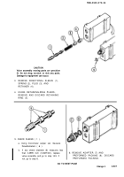
5. REMOVE THIRD RANGE RELAY
VALVE ASSEMBLY (1).
a. Using 3/8-inch drive ratchet handle,
extension, and 7/16-inch socket,
remove four screws (2).
b. Remove valve assembly (1).
c. Remove and discard gasket (3).
7. INSPECT DIRECTIONAL CONTROL
SLIDE (6) FOR FREE MOVEMENT
IN VALVE ASSEMBLY (1)
a. If slide (6) is stuck in valve assem-
bly (1), go to step 8. If not, go to
step 9.
8. REPAIR THIRD RANGE RELAY
VALVE ASSEMBLY, page 4-506.
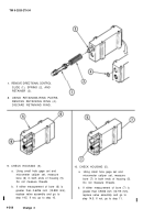
9. INSPECT MAIN HOUSING INSERTS.
6. REMOVE ADAPTER (4)
a. Place valve assembly (1) in vise.
b. Remove adapter (4) and preformed
packing (5).
c. Discard packing (5).
a. Inspect assembly, hardware, and
inserts. See page 2-5.
b. Repair inserts, if damaged. See
task REPAIR MAIN HOUSING
INSERTS, page 4-150.
GO TO NEXT PAGE
Change 2
4-503
TM 9-2520-270-34
Back to Top


