TM-9-2520-272-40 - Page 204 of 620
TM 9-2520-272-40
0025
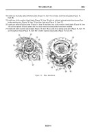
18.Install one internally splined (friction) plate (Figure 14, Item 19) on brake clutch backing plate (Figure 14,
Item 28).
19.Install one clutch reaction (steel) plate (Figure 14, Item 18) with six notched external projections around four
brake reaction pins (Figure 14, Item 13) and two f xed pins (Figure 14, Item 37).
20.Install one splined (friction) plate (Figure 14, Item 19) and then one clutch reaction (steel) plate (Figure 14, Item
18) until six splined (friction) plates and f ve clutch reaction (steel) plates have been installed.
21.Install end clutch reaction (steel) plate (Figure 14, Item 18) so ends of six spring guide pins (Figure 14, Item 17)
are through pin holes (Figure 14, Item 38) in clutch reaction (steel) plate (Figure 14, Item 18).
Back to Top


