TM-9-2520-272-40 - Page 333 of 620
TM 9-2520-272-40
0041
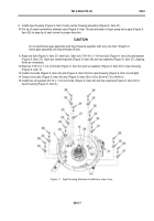
9. Install input housing (Figure 9, Item 3) onto center housing assembly (Figure 9, Item 21).
10.Put tip of small screwdriver between seal (Figure 9, Item 15) and shoulder of input pump drive gear (Figure 9,
Item 28) to keep lip of seal turned in proper direction.
CAUTION
Do not pull bevel gear assembly and input housing together with only one bolt. Weight of
bevel gear assembly will strip threads off bolt.
11. Align one bolt (Figure 9, Item 27) with hole. Start one 7/16-14 x 1-1/4 inch bolt (Figure 9, Item 26) and washer
(Figure 9, Item 27). Start two remaining bolts (Figure 9, Item 26) and two washers (Figure 9, Item 27), aligning
holes as necessary.
12.Start six 7/16-14 x 1-1/4 inch bolts (Figure 9, Item 24) and six washers (Figure 9, Item 25) in input housing
(Figure 9, Item 3).
13.Install nine bolts (Figure 9, Item 24) and (Figure 9, Item 26) into input housing (Figure 9, Item 3) until tight.
14.Torque nine bolts (Figure 9, Item 24) and (Figure 9, Item 26) to 54 to 65 lb-ft (73 to 88 N·m).
15.Install two zinc-plated 3/8-16 x 1-1/4 inch bolts (Figure 9, Item 23) and two washers (Figure 9, Item 22) in
input housing (Figure 9, Item 3).
Back to Top

