TM-9-2815-200-35
ENGINE, WITH CONTAINER:TURBOSUPERCHARGED, DIESEL ,FUEL INJECTION ,90-DEGREE “V” TYPE, AIR - COOLED ,12 - CYLINDER , ASSEMBLY ;MODELS AVDS-1790-2M (2815-856-4996), AVDS-1790-2A AND AVDS-1790-2AM (2815-856-9005)
TECHNICAL MANUAL; DIRECT SUPPORT, GENERAL SUPPORT AND DEPOT MAINTENANCE MANUAL INCLUDING REPAIR PARTS AND SPECIAL TOOLS LISTS
TM-9-2815-200-35 - Page 306 of 779
b. Disassembly.
Disassemble the crankcas e
and remove the crankcase from the overhau l
stand following instructions which accompan y
figures 6-5 through 6-8 .
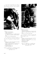
Remove
1. Remove two pipe plugs (A).
2. Remove four pipe plugs (B).
3. Remove pipe plug (C).
4. Cut locking wire and remove two drilled head bolts
(D) attaching fuel pump drive gearshaft replacement
cover.
5. Remove cover (E) and discard gasket.
Note.
Instructions covering pipe plugs (A )
and fuel pump driven gearshaft replacemen t
cover (E) are applicable to engines having a
cover .
Install
1. Position a new gasket and fuel pump driven gearshaft
replacement cover (E) on crankcase.
2. Install two drilled head bolts (D) securing cover to
crankcase and install locking wire securing bolts.
3. Install pipe plug (C).
4. Install four pipe plugs (B).
5. Install two pipe plugs (A).
Figure 6-5. Removing or installing pipe plug s
and fuel pump driven gearshaf t
replacement cover .
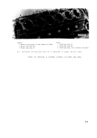
Remove
1. Remove pipe plug (A).
2. Remove pipe plug (B).
3. Remove three self-locking nuts (C) and flat washers
attaching fuel supply pump adapter replacement cover
(D).
4. Remove cover (D) and discard gasket.
Note.
Instructions covering fuel supply pump
adapter replacement cover (D) are applicable to
engines having a cover .
Install
1. Position a new gasket and fuel supply pump adapter
replacement cover (D) on crankcase.
2. Install three self-locking nuts (C) and flat washers
securing cover to crankcase.
3. Install pipe plug (B).
4. Install pipe plug (A).
Figure 6-6. Removing or installing pip e
plugs and fuel supply pump adapte r
replacement cover .
6-12
Back to Top


