TM-9-2815-200-35
ENGINE, WITH CONTAINER:TURBOSUPERCHARGED, DIESEL ,FUEL INJECTION ,90-DEGREE “V” TYPE, AIR - COOLED ,12 - CYLINDER , ASSEMBLY ;MODELS AVDS-1790-2M (2815-856-4996), AVDS-1790-2A AND AVDS-1790-2AM (2815-856-9005)
TECHNICAL MANUAL; DIRECT SUPPORT, GENERAL SUPPORT AND DEPOT MAINTENANCE MANUAL INCLUDING REPAIR PARTS AND SPECIAL TOOLS LISTS
TM-9-2815-200-35 - Page 314 of 779
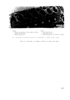
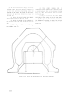
(2) To detect dimensional changes caused by
welding repair, precisely measure crankcase a t
several key positions depending upon th e
location of the repair. For repair to side walls ,
measure the positions outlined in steps (a )
through (d) .
(a) Across the main bearing cap suppor t
web machined surfaces (B, fig. 6-14) .
(b) Across the inside of the crankcase a t
the junction of the side wall and the oil pan rail
(D) .
(c) From oil pan rail face to main bearing
cap support face (C) .
(d)
From
cylinder
mounting
deck
to
crankshaft bearing support bore centerline using
a suitable plug or bore in the crankcase bearing
bore (A). This measurement shall be withi n
8.377-8.369 inch.
(e) Oil pan rail shall be flat within 0.010-
inch when all four corners are on the same plane.
(3) For repair in other locations, measure in
the appropriate locations to insure that critica l
dimensions are held. Record dimensions fo r
future use .
Figure 6-14. Points of measurement for checking crankcase .
6-2 0
Back to Top

