TM-9-2815-200-35
ENGINE, WITH CONTAINER:TURBOSUPERCHARGED, DIESEL ,FUEL INJECTION ,90-DEGREE “V” TYPE, AIR - COOLED ,12 - CYLINDER , ASSEMBLY ;MODELS AVDS-1790-2M (2815-856-4996), AVDS-1790-2A AND AVDS-1790-2AM (2815-856-9005)
TECHNICAL MANUAL; DIRECT SUPPORT, GENERAL SUPPORT AND DEPOT MAINTENANCE MANUAL INCLUDING REPAIR PARTS AND SPECIAL TOOLS LISTS
TM-9-2815-200-35 - Page 311 of 779
compound ,
FSN 9150-663-1770, to th e
threaded area of each main bearing cap stud .
Install a plate washer on each pair of mai n
bearing studs. Install a slotted nut on each main
bearing stud but do not tighten nuts at this time.
(h) Place a surface plate and dial in -
dicator gage on crankcase flange with gag e
indicator resting on end of stud. Measure an d
record height of each stud. Torque tighten main
bearing stud nuts to 500 pound-inches. Alter -
nately tighten all four nuts on each main bearing
to a torque of 700-825 pound-inches. Measur e
the height of each stud after final torque. The
difference between the stud height before an d
after torque tightening, indicates stud stretch .
Normal stud stretch is 0.010 to 0.022-in. If any
stud has stretched more than 0.024-in. at 70 0
pound-inches torque, it must be replaced. Refe r
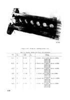
to table 6-3 when replacing studs .
(i) Install the 14 crankcase tie rods in the
holes provided through the crankcase and main
bearing caps. Equalize the extension of th e
threaded portions of the tie rods on each side of
the crankcase. Apply a small amount of antiseize
compound ,
FSN 9150-663-1770, to th e
threaded portions of each tie rod. Install a plate
washer and a 9 / 16 slotted nut on each end o f
the tie rods .
(j) Starting at the main thrust bearin g
cap, with aid of an assistant to hold the nuts on
the opposit e
side of crankcase ,
alternatel y
tighten all main bearing cap tie rod nuts to 640
pound-inches torque.
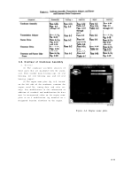
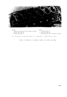
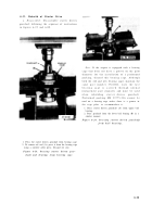
(k) Check the inside diameter of the main
bearings with a dial bore indicator as shown in
figure 6-12 against the limits specified i n
overhaul standards (table 6-2). Replace bearing s
which do not meet these requirements. Ne w
bearings must also be dial bore checked. Remove
the main bearing caps and bearing halves fro m
the crankcase and check contact surface a s
indicated by Prussian blue, FSN 8010-847 -
8706 transfer. Replace bearings that do no t
make 75 percent contact with crankcase bearing
bores. Repeat dial bore check of new bearing s
installed .
Figure 6-12 . Checking inside diameter o f
main bearings .
6-1 7
Back to Top

