TM-9-2815-200-35
ENGINE, WITH CONTAINER:TURBOSUPERCHARGED, DIESEL ,FUEL INJECTION ,90-DEGREE “V” TYPE, AIR - COOLED ,12 - CYLINDER , ASSEMBLY ;MODELS AVDS-1790-2M (2815-856-4996), AVDS-1790-2A AND AVDS-1790-2AM (2815-856-9005)
TECHNICAL MANUAL; DIRECT SUPPORT, GENERAL SUPPORT AND DEPOT MAINTENANCE MANUAL INCLUDING REPAIR PARTS AND SPECIAL TOOLS LISTS
TM-9-2815-200-35 - Page 495 of 779
Section XIV. OVERHAUL OF GENERATOR AND STARTE R
SUPPORTS, FUEL CHECK VALVE, PRIMARY AND SECONDAR Y
FUEL FILTERS, AND FUEL / WATER SEPARATO R
6-54. Genera l
assembly accompany the overhaul operations .
This section covers the overhaul of th e
Stud identification information is included in the
generator and starter supports, fuel check valve ,
overhaul procedures where applicable. Refer to
primary and secondary fuel filters, an d
the following table (table 6-42) for applicabl e
fuel / water separator. Specific instructions on
illustration s
an d
instructions for overhau l
disassembly, cleaning, inspection, repair, an d
operations .
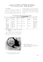
Table 6-42. Generator and Starter Supports, Fuel Check Valve, Primary
Generator and
Starter Sup-
ports
Fuel Check
Valve
and Secondary Fuel Filters, and Fuel / Water Separator
Disassembly
Primary and
Secondary
Fuel Filters
Fuel / Water
Separator
and Fuel
Drain Tubes
6-55. Overhaul of Generator and Starte r
Support s
a. Disassembly.
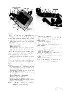
Disassemble generato r
support following instructions which accompany
figure 6-240. The starter support wa s
disassembled during starter removal, Chapter 4 .
Para 6-55a
Fig. 6-240
Para 6-56a
Figs. 6-241,
6-242
Para 6-57a
Figs. 6-244,
6-245
Para 6-58a
Figs. 6-246,
6-247
Cleaning
Para 6-2
Para 6-2
Para 6-57b
Para 6-58b
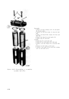
Figure 6-240. Disassembling generato r
cradle, support, and “U” bolt .
Inspection
Para 6-3
Para 6-3
Para 6-57b
Para 6-58b
Repair
Para 6-4
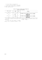
Table 6-43
Para 6-4
Para 6-57b
Para 6-58b
Assembly
Para 6-55d
Fig. 6-240
Para 6-56c and
Figs. 6-242,
6-241,6-243
Para 6-57c
Figs. 6-245,
6-244
Para 6-58c
Figs. 6-247,
6-246
1. Remove self-locking nut (A).
2. Remove clamping bar (B) and “U” bolt.
3. Remove two self-locking nuts (C) and flat washers
attaching cradle to support.
6-201
Back to Top


