TM-9-2815-200-35
ENGINE, WITH CONTAINER:TURBOSUPERCHARGED, DIESEL ,FUEL INJECTION ,90-DEGREE “V” TYPE, AIR - COOLED ,12 - CYLINDER , ASSEMBLY ;MODELS AVDS-1790-2M (2815-856-4996), AVDS-1790-2A AND AVDS-1790-2AM (2815-856-9005)
TECHNICAL MANUAL; DIRECT SUPPORT, GENERAL SUPPORT AND DEPOT MAINTENANCE MANUAL INCLUDING REPAIR PARTS AND SPECIAL TOOLS LISTS
TM-9-2815-200-35 - Page 498 of 779
Note.
Components of the fuel check valve ar e
not available as replacement parts. Therefore, no
further disassembly is required .
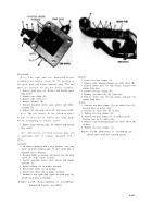
Figure 6-242. Deleted .
b. Cleaning, Inspection and Repair.
Refer t o
paragraphs 6-2, 6-3, and 6-4 .
c.
Assembly.
Refer to figure 6-241 .
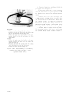
d. Test and Adjustment
(fig. 6-243) .
(1) Fill valve with test fluid, MIL-F-7024 A
Type II, and apply a pressure of ½ psi to por t
marke d
“FREE FLOW” (fuel inlet fro m
primary fuel filter). The check valve must open
at this pressure . Valve operation can be deter -
mined when fluid flows from the fuel pum p
outlet port .
(2) Apply a pressure of 85 to 95 psi to the
heater pump inlet port. The check ball mus t
bypass fluid at this pressure. Adjust socket head
adjusting screw (F, fig. 6-242) to obtain thi s
opening pressure .
(3) Plug the fuel pump outlet port, and the
heater pump outlet port, and apply a pressure o f
100 psi at heater pump inlet port. There should
be no fuel leakage from the “FREE FLOW ”
port .
(4) If the valve fails to pass either test ,
replace entire valve assembly .
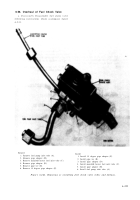
Figure 6-243. Fuel check valve flow diaphragm .
6-204
Back to Top


