TM-9-2815-200-35
ENGINE, WITH CONTAINER:TURBOSUPERCHARGED, DIESEL ,FUEL INJECTION ,90-DEGREE “V” TYPE, AIR - COOLED ,12 - CYLINDER , ASSEMBLY ;MODELS AVDS-1790-2M (2815-856-4996), AVDS-1790-2A AND AVDS-1790-2AM (2815-856-9005)
TECHNICAL MANUAL; DIRECT SUPPORT, GENERAL SUPPORT AND DEPOT MAINTENANCE MANUAL INCLUDING REPAIR PARTS AND SPECIAL TOOLS LISTS
TM-9-2815-200-35 - Page 493 of 779
6-53 .
Exhaust Manifolds, Cylinder Hea d
Oil Drain Tubes, and Oi l
Filler and Oil Level Indicato r
Tube s
a. Disassembly .
(1)
Exhaust
manifolds
and
cylinder
head
oil
drain tubes.
Disassembly of exhaust manifold s
and cylinder head oil drain tubes was ac -
complished during engine disassembly, Chapte r
5 .
(2)
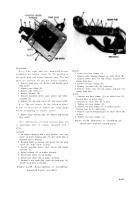
Oil filler and oil level indicator tubes .
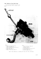
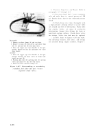
Refer to figures 6-237 through 6-239 .
Note.
Due to design changes, two different oil
level indicator tubes and three different oil filler
tubes have been used on the engine. Basi c
disassembly procedures are the same for eac h
tube design .
Disassemble
Assemble
1. Remove cap spring (A).
1. Position seal (C) on oil filler tube only.
2. Do not remove cap shoulder bolts (B) unless in-
2. If necessary, install new cap shoulder bolts (B) and
spection (para 6-53c) indicates replacement is
stake in place.
necessary. Bolts are staked in place.
3. Install cap spring (A).
3. Remove and discard seal (C). Oil filler tube only.
Figure 6-237. Disassembling or assembling oil filler and oil leve l
indicator tubes (one piece oil filler and indicator tube s
without splash pan drain) .
6-199
Back to Top

