TM-9-2815-200-35
ENGINE, WITH CONTAINER:TURBOSUPERCHARGED, DIESEL ,FUEL INJECTION ,90-DEGREE “V” TYPE, AIR - COOLED ,12 - CYLINDER , ASSEMBLY ;MODELS AVDS-1790-2M (2815-856-4996), AVDS-1790-2A AND AVDS-1790-2AM (2815-856-9005)
TECHNICAL MANUAL; DIRECT SUPPORT, GENERAL SUPPORT AND DEPOT MAINTENANCE MANUAL INCLUDING REPAIR PARTS AND SPECIAL TOOLS LISTS
TM-9-2815-200-35 - Page 494 of 779
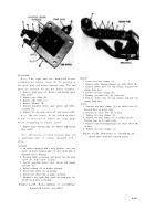
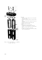
Disassemble
1. Remove two machine bolts (A) and lock washers
attaching cap assembly to left front upper cover and
remove cap.
2. Remove and discard cap gasket (B).
3. Remove and discard two preformed packings (C)
from cap.
4. Remove and discard preformed packing (D).
5. Remove cap spring (E).
6. Remove machine bolt (F) and remove cap (G).
Assemble
1. Position cap (G) on cap assembly and install machine
bolt (F).
2. Install cap spring (E).
3. Install a new preformed packing (D).
4. Position two preformed packings (C) on cap
assembly.
5. Position a new cap gasket (B) on left front upper
cover.
6. Install two machine bolts (A) and lock washers,
securing cap assembly to upper cover.
Figure 6-238. Disassembling or assemblin g
oil filler and oil level indicator tube s
(improved oil filler indicator tube s
with splash pan drain) .
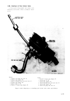
Note.
Refer to figure 6-238 for disassembly or
assembly procedures of the relocated oil fille r
tube .
b. Cleaning.
Refer to paragraph 6-2 .
c.
Inspection and Repair.
Refer to paragraph s
6-3
and
6-4,
and
(1)
and
(2),
below.
(1) Inspect exhaust manifold s
broken welds, damaged bellows ,
flanges .
6-20 0
for cracks ,
and ben t
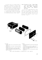
Disassemble
1. Remove two machine bolts (A) and lock washers
attaching cap assembly to left front upper cover and
remove cap.
2. Remove and discard cap gasket (B).
3. Remove and discard two preformed packings (C)
from cap.
4. Remove and discard preformed packing (D).
5. Remove cap spring (E).
6. Remove machine bolt (F) and remove cap (G).
Assemble
1. Position cap (G) on cap assembly and install machine
bolt (F).
2. Install cap spring (E).
3. Install a new preformed packing (D).
4. Position two preformed packings (C) on cap
assembly.
5. Position a new cap gasket (B) on left front upper
cover.
6. Install two machine bolts (A) and lock washers,
securing cap assembly to upper cover.
Figure 6-239. Disassembling or assemblin g
oil level indicator tube cap (relocated
oil filler tube) .
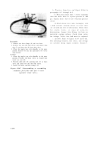
(2) Inspect cap shoulder bolts (B, fig. 6 -
237) for looseness or damaged shoulder area .
d. Assembly.
Refer to figures 6-237 through 6-
239 for assembly of oil filler and oil level in -
dicator tubes and caps. Exhaust manifolds an d
cylinder head oil drain tubes will be assembled
during engine assembly, Chapter 7 .
Back to Top

