TM-9-2815-200-35
ENGINE, WITH CONTAINER:TURBOSUPERCHARGED, DIESEL ,FUEL INJECTION ,90-DEGREE “V” TYPE, AIR - COOLED ,12 - CYLINDER , ASSEMBLY ;MODELS AVDS-1790-2M (2815-856-4996), AVDS-1790-2A AND AVDS-1790-2AM (2815-856-9005)
TECHNICAL MANUAL; DIRECT SUPPORT, GENERAL SUPPORT AND DEPOT MAINTENANCE MANUAL INCLUDING REPAIR PARTS AND SPECIAL TOOLS LISTS
TM-9-2815-200-35 - Page 484 of 779
6-48. Overhaul of Engine Cooling Fan
and Associated
Parts
housing were removed during disassembly,
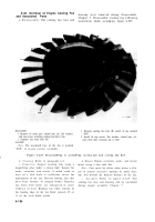
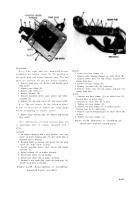
Chapter 5. Disassemble cooling fan following
instructions which accompany figure 6-225.
a.
Dissassembly.
The cooling fan vane and
Disassemble
1. Position cooling fan hub (B) inside of fan marked
1. Remove 16 cotter piss, slotted nuts (A), flat washers,
“TOP”.
and cap screws attaching cooling fan hub to fan.
2. Separate fan from hub (B).
2. Install 16 cap screws, flat washers, slotted nuts (A),
Assemble
and cotter pins securing fan to hub.
Note.
The machined face of the fan is marked
“TOP” to insure correct assembly.
Figure 6-225. Disassembling or assembling cooling fan and cooling fan hub.
b. Cleaning.
Refer to paragraph 6-2.
c. Inspection.
Inspect cooling fans using a
magnifying glass under a strong light. Inspect for
nicks, scratches, and cracks. A radial crack in
area of a bolt hole is sufficient cause fo r
replacement of the fan. Discard cooling fans that
have bent, broken, or warped blades. Replace
fan when bolt holes are elongated or sho w
evidence of wear. Replace fan when erosion of
the leading edge of the fan blade exceeds 25 or
¼ of the total blade width.
6-190
d. Repair.
Repair scratches, nicks, and raised
metal using a fine mill file.
Note.
Care must be taken when using a file,
not to remove excessive amounts of metal since
this will disturb the delicate balance of the fan.
e. Assembly.
Refer to figure 6-225. Th e
cooling fan vane and housing will be assembled
during engine assembly, Chapter 7.
Back to Top


