TM-9-2815-200-35
ENGINE, WITH CONTAINER:TURBOSUPERCHARGED, DIESEL ,FUEL INJECTION ,90-DEGREE “V” TYPE, AIR - COOLED ,12 - CYLINDER , ASSEMBLY ;MODELS AVDS-1790-2M (2815-856-4996), AVDS-1790-2A AND AVDS-1790-2AM (2815-856-9005)
TECHNICAL MANUAL; DIRECT SUPPORT, GENERAL SUPPORT AND DEPOT MAINTENANCE MANUAL INCLUDING REPAIR PARTS AND SPECIAL TOOLS LISTS
TM-9-2815-200-35 - Page 481 of 779
c. Cleaning .
(1) External surfaces of coolers may b e
cleaned using oil cooler cleaning tool - 2940-927-
3303. Clean thoroughly and blow dry wit h
compressed air at 15 psi pressure .
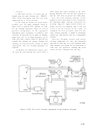
(2) To clean the interior of an oil coole r
assembly core, the pump equipment shown i n
figure 6-224 is required. Four solutions are used
for the cleaning procedure. There are severa l
possibl e
arrangements of the equipmen t
depending upon equipment availability an d
versatility. If provision can be made for flushing
pump lines, one set of pump equipment can b e
used with four storage tanks to provide th e
required four solutions for rinsing, cleaning,
an d
flushing. If such provisions cannot be mad e
conveniently, four sets of pump equipment ar e
required .
(3) Remove the thermostatic bypass valv e
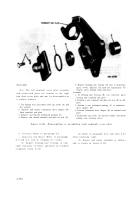
(A) from the valve housing (fig. 6-223). Press a
rubber plug into bypass opening in the valv e
housing. Reinstall valve into the valve housing so
that the valve bears up against the rubber plug .
Note.
Use only cleaning solutions recom -
mended in these instructions or ones satisfactory
for aluminum . Many solutions satisfactory fo r
cleaning copper or copper nickel coolers ar e
highly corrosive to aluminum and if used wil l
result in the destruction of the cooler. I f
equipment has been previously used with an y
other cleaning solutions, it should be thoroughly
washed out and flushed with the recommende d
solution .
Warning;
Cleaning solvents and solven t
cleaning compounds are toxic and flammabl e
and must be used only in a well ventilated room.
Take adequate safe guards for fire prevention in
work area. Use protective clothing and avoi d
contact of these solutions with the skin .
Figure 6-224. Oil cooler cleaning equipment setup-schematic diagram .
6-187
Back to Top


