TM-9-2815-200-35
ENGINE, WITH CONTAINER:TURBOSUPERCHARGED, DIESEL ,FUEL INJECTION ,90-DEGREE “V” TYPE, AIR - COOLED ,12 - CYLINDER , ASSEMBLY ;MODELS AVDS-1790-2M (2815-856-4996), AVDS-1790-2A AND AVDS-1790-2AM (2815-856-9005)
TECHNICAL MANUAL; DIRECT SUPPORT, GENERAL SUPPORT AND DEPOT MAINTENANCE MANUAL INCLUDING REPAIR PARTS AND SPECIAL TOOLS LISTS
TM-9-2815-200-35 - Page 479 of 779
Table 6-37. Engine and Transmission Oil Coolers and Engine Cooling Fan
Component
Disassembly
Cleaning
Inspection
Repair
Engine and
Transmis-
sion Oil
Coolers
Engine
Cooling
Fa n
Para 6-47b
Figs. 6-221
through
6-223
Para 6-48a
Fig. 6-225
Para 6-47c
Fig. 6-224
Para 6-2
Para 6-47d
Para 6-48c
Para 6-47e
Table 6-38
Para 6-48d
Assembly
Para 6-47f
Figs. 6-223
through
6-221
Para 6-48e
Fig. 6-225
6-47. Overhaul of Engine and Trans -
mission Oil Cooler and Associ -
ated Part s
a. General.
The engine oil coolers are identical
and so are the transmission oil coolers. Adap -
tation to either right or left installation is ac -
complished by the addition of hose connections ,
elbows, and bypass valves. For instructiona l
purposes, the engine and transmission oil cooler s
adapted for right bank installation will b e
disassembled .
b. Disassembly.
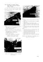
Disassemble engine an d
transmission oil coolers following instruction s
which accompany figures 221 through 223 .
Remove
1. Remove transmission oil cooler bypass valve (A).
Remove and discard valve gasket.
2. Remove two assembled washer bolts (B) and remove
oil cooler shroud plate.
Install
1. Position oil cooler shroud plate on transmission oil
cooler and install two assembled washer bolts (B).
2. Position a new valve gasket on cooler and install
transmission oil cooler bypass valve (A).
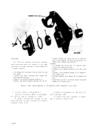
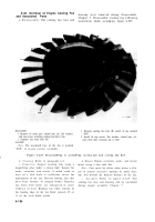
Figure 6-221. Removing or installin g
transmission oil cooler bypas s
valve and shroud plate .
6-18 5
Back to Top


