TM-9-2815-200-35
ENGINE, WITH CONTAINER:TURBOSUPERCHARGED, DIESEL ,FUEL INJECTION ,90-DEGREE “V” TYPE, AIR - COOLED ,12 - CYLINDER , ASSEMBLY ;MODELS AVDS-1790-2M (2815-856-4996), AVDS-1790-2A AND AVDS-1790-2AM (2815-856-9005)
TECHNICAL MANUAL; DIRECT SUPPORT, GENERAL SUPPORT AND DEPOT MAINTENANCE MANUAL INCLUDING REPAIR PARTS AND SPECIAL TOOLS LISTS
TM-9-2815-200-35 - Page 474 of 779
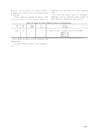
Table 6-34. Camshafts and Drives Overhaul Standards
Component
Camshafts
Camshafts
Upper
cam-
shaft drive quill
bevel
gear-
shafts
Camshaft drive
quills
Camshaft drive
quills
Camshaft end
plate
Fig
No.
—
B-5
B-4
B-4
B-5
B-5
B-5
B-5
B-5
B-5
B-5
B-5
B-5
B-5
B-5
B-5
B-5
B-5
B-5
B-5
B-5
B-5
B-5
B-26
B-26
B-5
B-5
B-5
B-5
Ref.
letter
L
X
X-L
N
Q
Q-N
M
K
G
G-K
B
F
F-B
C
E
E-C
A
D
D-A
UU
UU-A
J
H
H-J
Point of measurement
Outside diameter of journal on camshaft
Inside diameter of camshaft bearing in cylinder
Fit of journal in bearing
Maximum out-of-round of camshaft journal
(full indicator reading)
Maximum runout of center journal when
supported on end bearing (full indicator
reading)
Outside diameter of camshaft pilot bearing at
end plate
Inside diameter of split bushing-type bearing in
camshaft end plate
Fit of camshaft pilot in end plate bushing-type
bearing
Camshaft lobe lift
Outside diameter of large journal on end of
camshaft
Inside diameter of bearing surface in camshaft
gear housing
Fit of journal in bearing
Outside diameter of hub on gearshaft
Inside diameter of bore in upper adapter
Fit of hub in adapter bore
Inside diameter of hub on gearshaft
Outside diameter of upper oil transfer plug
Fit of plug in hub
Inside diameter of quill (both ends)
Spherical outside diameter of upper oil transfer
plug
Fit of upper quill plug in quill bore
Spherical outside diameter of lower oil transfer
plug
Fit of lower quill plug in quill bore
Outside diameter of oil seal
Inside diameter of camshaft end plate
Fit of oil seal in end plate bore
Sizes and fits
of new Parts
1.3090
1.3100
1.3120
1.3130
0.0020L 0.0040L
0.0010
0.0020
1.3090
1.3100
1.3120 1.313 0
0.0020L 0.0040 L
0.4030
0.4090
2.4965
2.4975
2.5000
2.5010
0.0025L 0.0045 L
1.6220
1.6230
1.6250
1.6260
0.0020L 0.0040 L
1.2710
1.2720
1.2700
1.2705
0.0005L 0.0020 L
0.6295 0.630 5
0.6275
0.6280
0.0015L 0.0030 L
0.6275
0.6280
0.0015L 0.0030 L
1.5010
1.5050
1.4990
1.5000
0.0010T 0.0060 T
Note.
Refer to paragraph 6-3b for explanation
of symbols .
Table 6-35. Camshaft Drive Housing and Cover Plate Standard and Oversize
Stud Identification
Fig.
No.
B-5
B-5
Ref.
No.
29
40
Setting
height
1-5 / 32
3/ 4
No.
req’d
8
4
Wear limits
1.3085
1.3135
0.0050L
0.0020
0.0150
*
*
*
0.4000
2.4960
2.5020
0.0065L
1.6210
1.6270
*
*
*
*
0.6320
0.6265
0.0060L
0.6265
0.0060L
*
*
*
Stud size
Length
3 / 8-16 (15 / 16) x 3 / 8-24 (13 / 16) x 1-15 / 16 (STD)
(0.003 in. OS)
(0.007 in. OS)
(0.012 in. OS)
1 / 4-20 (19 / 32) x 1 / 4-28 (21 / 32) x 1-5 / 16 (STD)
(0.003 in. OS)
(0.007 in. OS)
(0.012 in. OS)
Note.
Refer to figure 6-1 for oversize stu d
d. Assembly.
Refer to figures 6-213 through 6-
identification .
207 .
6-180
Back to Top


