TM-9-2815-200-35
ENGINE, WITH CONTAINER:TURBOSUPERCHARGED, DIESEL ,FUEL INJECTION ,90-DEGREE “V” TYPE, AIR - COOLED ,12 - CYLINDER , ASSEMBLY ;MODELS AVDS-1790-2M (2815-856-4996), AVDS-1790-2A AND AVDS-1790-2AM (2815-856-9005)
TECHNICAL MANUAL; DIRECT SUPPORT, GENERAL SUPPORT AND DEPOT MAINTENANCE MANUAL INCLUDING REPAIR PARTS AND SPECIAL TOOLS LISTS
TM-9-2815-200-35 - Page 468 of 779
Table 6-33. Camshaft and Throttle Control Cross Shaft and Fuel Injection Pump Linkage
Component
Camshaft and
Associated
Parts
Throttle Con-
trol Cross
Shaft and Fuel
Injection Pump
Linkage
Disassembly
Para 6-44a
Figs. 6-207
through
6-213
Para 6-45a
Figs. 6-215
through
6-220
6-44. Overhaul of Camshaft
Cleaning
Para 6-2
Para 6-2
Inspection
Para 6-44c
Table 6-34
Para 6-3
Table 6-36
Repair
Para 6-44c
Table 6-35
Fig. 6-214
Para 6-4
Assembly
Para 6-44d
Figs. 6-213
through 6-207
Para 6-45d
Figs. 6-220
through 6-215
following instructions which accompany figures
a. Disassembly.
Disassemble camshaft
6-207 through 6-213.
Remove
Install
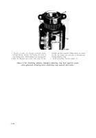
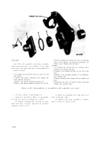
1. Remove lifting eye (A), preformed hose, and in-
1. Position rubber hose on camshaft drive abaft flange
tercylinder hose flange, and separate the liiting eye and
and install two hose clamps (D).
flange from hose.
2. Position a new camshaft end cover plate gasket (C) on
2. Remove the remaing four groups of intercylinder hose
camshaft.
flanges (B) and preformed hoses and separate tbe
3. Position two intercylinder hose flanges (B) on each of
flanges from hoses.
four preformed hoses and position hose assemblies on
3. Remove and discard the camshaft end cover plate
camshaft.
gasket (C).
4. position lifting eye (A) and remaining intercylinder
4. Remove two hose clamps (D) and the rubber hose
hose flange on remaining preformed hose and position
from camshaft drive shaft flange.
hoee assembly on camshaft.
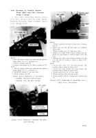
Figure 6-207. Removing or installing lifting eye, intercylinder hose
flanges, and hoses.
6-174
Back to Top

