TM-9-2815-200-35
ENGINE, WITH CONTAINER:TURBOSUPERCHARGED, DIESEL ,FUEL INJECTION ,90-DEGREE “V” TYPE, AIR - COOLED ,12 - CYLINDER , ASSEMBLY ;MODELS AVDS-1790-2M (2815-856-4996), AVDS-1790-2A AND AVDS-1790-2AM (2815-856-9005)
TECHNICAL MANUAL; DIRECT SUPPORT, GENERAL SUPPORT AND DEPOT MAINTENANCE MANUAL INCLUDING REPAIR PARTS AND SPECIAL TOOLS LISTS
TM-9-2815-200-35 - Page 461 of 779
(a) Check fuel level and oil level gage s
(figure 6-199c). Fill supply tank (s) if either gage
indicates less than half full (use oil, specification
MIL-L-45199 (Grade 30) or fuel, specificatio n
VV-L-800) .
(b) Check to insure that the maste r
switch, the oil heater switch, the jog run (clutch
engage) switch, and the motor switch are all in
the “OFF” position and that the speed regulato r
control is at zero (0) .
(c) Turn master switch handle to th e
“ON” position. Note that power indicator ligh t
comes on. If power indicator light does not light,
press the reset buttons. If light still does no t
operate, investigate and correct the deficienc y
before starting .
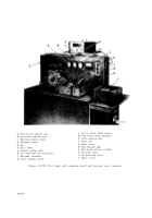
Figure 6-199c. Test stand heater control an d
supply tanks .
(d) Turn oil heater (thermostat) control ,
figure 6-199c, to a setting of 250 degrees and
turn oil heater switch, figure 6-199b “ON”. The
oil heater indicator lamp will light when th e
heater switch is turned on and will go out when
the oil has reached the selected oil temperature
heater control setting (250 degrees) .
(e) Turn the electronic counter switch ,
figure 6-199b, “ON”. The electronic com -
ponents in the counter will reach operatin g
temperature by the time the test is begun .
(f) Loosen fasteners and remove fue l
injection pump drive housing cover from top o f
test stand. Remove the two bearing caps an d
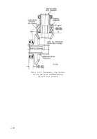
intermediate bearing support from the mounting
fixture, figure 6-201 .
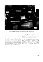
(g) Install retaining ring on oil retaining
shaft. Install short (stub) end of oil retainin g
shaft in driven (small) end of the advanc e
assembly. Install support over bearing on large
gear end of advance assembly and install ad -
vance assembly in bearing supports of mounting
fixture and secure with hardware remove d
above. Install drive housing cover and secur e
with fasteners .
Caution:
The fuel injector pump advanc e
assembly drive housing cover must always b e
installed and secured before operating test stand.
(h) Push jog run (clutch engage) switch to
engage eddy current clutch and turn spee d
regulator control to obtain advance assembl y
speed of 300 rpm on tachometer. Turn spee d
regulator control clockwise to increase rpm .
(i) Observe oil and fuel pressure in -
dicator gages, figure 6-199b. These gages should
register more than zero (0); however, maximu m
pressures will not be evident until a speed o f
2000 rpm is obtained .
Caution:
Turn master switch handl e
“OFF” if there is no indication of oil or fue l
pressure on the gages. Investigate and correct the
deficiency before starting the test .
(j) Operate test stand at 300 rpm until the
oil temperature dial thermometer (H) stabilize s
at 250 degrees. It may require several minutes to
warm the entire system to operating tem -
perature. Note and record electronic counter (K )
reading (illuminated decimal digits on the fron t
of the counter panel) .
(k) Press oil drain push switch, locate d
immediately
below
the
oil
pressure
indicator
gage. The gage should register zero (0) psi with
the switch depressed. observe the counte r
reading. If the counter has changed more tha n
one (1) degree, the advance assembly require s
adjustment .
(1) Release oil pressure drain switch .
Turn
speed
regulator
control
clockwise
to
in-
crease the speed to 600 rpm. Note and record the
6-167
Back to Top


