TM-9-2815-200-35
ENGINE, WITH CONTAINER:TURBOSUPERCHARGED, DIESEL ,FUEL INJECTION ,90-DEGREE “V” TYPE, AIR - COOLED ,12 - CYLINDER , ASSEMBLY ;MODELS AVDS-1790-2M (2815-856-4996), AVDS-1790-2A AND AVDS-1790-2AM (2815-856-9005)
TECHNICAL MANUAL; DIRECT SUPPORT, GENERAL SUPPORT AND DEPOT MAINTENANCE MANUAL INCLUDING REPAIR PARTS AND SPECIAL TOOLS LISTS
TM-9-2815-200-35 - Page 463 of 779
6-169
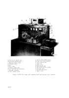
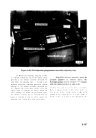
Figure 6-201
6-31
(t) Rotate the adjusting ring (fig. 6-201 )
1 / 16-inch toward the rear of the bench (retard
position) if the advance assembly advanced too
soon. Move the adjusting ring 1 / 16-inch in the
opposite direction (advance position) towar d
operator, if the advance assembly advanced too
late. Tighten the slotted nuts, install cover and
repeat steps (c) through (h), above. When ad -
vance readings are within the prescribed limits .
the advance assembly may be removed from th e
bench as outlined in step (i), above. Secure the
adjusting ring slotted nuts with cotter pins .
(5)
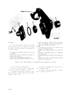
Rear fan and accessory drive assembly .
Refer to figures 6-154, 6-155, 6-188, 6-151, 6 -
152, 6-153, 6-189, 6-190, 6-172, 6-202 6-17 0
through 6-168, 6-203, 6-153, or 6-152, 6-204 o r
6-205, 6-164, or 6-162, 6-161 through 6-159 .
Back to Top


