TM-9-2815-200-35
ENGINE, WITH CONTAINER:TURBOSUPERCHARGED, DIESEL ,FUEL INJECTION ,90-DEGREE “V” TYPE, AIR - COOLED ,12 - CYLINDER , ASSEMBLY ;MODELS AVDS-1790-2M (2815-856-4996), AVDS-1790-2A AND AVDS-1790-2AM (2815-856-9005)
TECHNICAL MANUAL; DIRECT SUPPORT, GENERAL SUPPORT AND DEPOT MAINTENANCE MANUAL INCLUDING REPAIR PARTS AND SPECIAL TOOLS LISTS
TM-9-2815-200-35 - Page 472 of 779
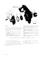
Disassemble
Note.
The left camshaft cover plate assembly
and associated parts are similar to the righ t
cam shaft cover plate and may be disassembled in
a similar manner .
1. Cut locking wire and remove four cap screws (A) and
flat washers.
2. Separate and remove tachometer drive adapter (B)
from camshaft end plate.
3. Remove and discard preformed packing (C).
4. Remove, and discard camshaft end plate oil seal (D).
5. Remove bushing-type bearing (E) only if inspection
(para. 6-44c) indicates the need for replacement. To
remove, press bearing from end plate.
Assemble
1. If bushing-type bearing (E) was removed, press
bearing into camshaft end plate.
2. Position a new camshaft end plate oil seal (D) in end
plate.
3. Position a new preformed packing (C) in tachometer
drive adapter (B).
4. Position tachometer drive adapter (B) on camshaft end
plate.
5. Install four cap screws (A) and flat washers and install
locking wire securing screws.
Figure 6-213. Disassembling or assembling right camshaft cover plate .
b. Cleaning.
Refer to paragraph 6-2 .
(2) Refer to paragraph 6-4e and table 6-35
c. Inspection and Repair.
Refer to paragraph s
when replacing studs .
6-3 and 6-4, and (1) through (3), below .
(3) Inspect and repair camshaft as follow s
(1) Inspect bushing-type bearing in cam -
and as shown in figure 6-214 .
shaft end plate to limits specified in overhau l
standards (table 6-34) .
6-17 8
Back to Top


