TM-9-2815-200-35
ENGINE, WITH CONTAINER:TURBOSUPERCHARGED, DIESEL ,FUEL INJECTION ,90-DEGREE “V” TYPE, AIR - COOLED ,12 - CYLINDER , ASSEMBLY ;MODELS AVDS-1790-2M (2815-856-4996), AVDS-1790-2A AND AVDS-1790-2AM (2815-856-9005)
TECHNICAL MANUAL; DIRECT SUPPORT, GENERAL SUPPORT AND DEPOT MAINTENANCE MANUAL INCLUDING REPAIR PARTS AND SPECIAL TOOLS LISTS
TM-9-2815-200-35 - Page 473 of 779
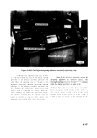
Figure 6-214. Improvised camshaf t
trueing device .
(a)
Checking camshaft bearing journa l
run-out.
Camshafts may be straightened if th e
runout of any one camshaft bearing surfac e
(journal), when using a dial indicator, does no t
exceed 0.060 inch total indicator reading (TIR )
when supported at the two adjacent bearin g
journals. Camshafts that exceed 0.060 inc h
runout between any two journals must b e
discarded. Maximum journal runout o f
straightened camshafts is 0.002 inch (TIR )
when supported at the two adjacent journals .
After straightening a camshaft, the maximu m
acceptable runout of the center bearing journal ,
when supported at the end journals, is 0.01 5
inch (TIR). Check camshaft bearing journa l
runout as follows :
(1)
Support the camshaft at the tw o
end journals in “V” blocks on a surface plate or
other available centering device, such as a
machine lathe .
(2)
Position a dial indicator at th e
center bearing journal and obtain a zero reading
on the dial .
(3)
Rotate the camshaft and determine
the maximum travel of the dial indicator needle .
If travel (TIR) exceeds 0.015 inch the camshaf t
must be straightened .
(4)
Repeat steps
(2)
and
(3),
above fo r
each bearing journal and mark position an d
dimension of maximum dial indicator reading a t
(5)
Check runout of each camshaf t
bearing journal. Support the camshaft in “V ”
blocks at the adjacent journals, and using a dia l
indicator ,
check and record journal runou t
(TIR) dimensions. If runout exceeds 0.002 inch ,
cam shaft must be straightened .
(b)
Straightening camshaft .
(1)
Install camshaft on trueing device
with bearing journal having the maximu m
runout (TIR) positioned under the pressin g
spindle. (The camshaft journals must be resting
on the support blocks when rotating the cam -
shaft to determine the runout.) Set dial on in -
dicator to “zero ”
and rotate camshaft t o
determine location of runout (TIR) and recor d
reading .
(2)
Turn camshaft until bearin g
journal marked to indicate the maximum runou t
(high side) is adjacent to the spindle (do no t
press on journals). Apply spindle pressure on the
camshaf t
until dial indicator reads ap -
proximately on e
half of the TIR readin g
recorded in (a), above. Release pressure o n
cam shaft and recheck runout by turnin g
camshaft several revolutions .
Note.
Pressing force required to straighte n
cam shaft is a matter of judgement. It may b e
necessary to turn camshaft and apply pressin g
force several times in order to acquire th e
technique necessary to true the bearing journal .
(3)
Apply pressure as required until the
journal is within the 0.002 maximum TIR .
(4)
Reposition camshaft on support s
and true other bearing journals is a simila r
manner .
(5)
After trueing all bearing journals ,
recheck camshaft as outlined in procedure (a) ,
above. If readings do not meet dimension s
specified, repeat trueing operation .
(c)
Inspection of camshaft afte r
straightening .
(1)
Magnaflu x
each camshaft an d
inspect for cracks. Observe transition areas a t
bearing surfaces and at cam lobe bases. Cam -
shafts with evidence of cracks must be discarded.
(2)
Inspect for damage to bearin g
journals .
Minor nicks and scratches can b e
removed using crocus cloth .
(3)
Check bearing journals for out-of -
round to be certain area was not flattened during
trueing .
Maximum acceptable out-of-round i s
0.002 inch (TIR). Replace camshaft if thi s
tolerance is exceeded .
6-179
Back to Top


