TM-9-2815-200-35
ENGINE, WITH CONTAINER:TURBOSUPERCHARGED, DIESEL ,FUEL INJECTION ,90-DEGREE “V” TYPE, AIR - COOLED ,12 - CYLINDER , ASSEMBLY ;MODELS AVDS-1790-2M (2815-856-4996), AVDS-1790-2A AND AVDS-1790-2AM (2815-856-9005)
TECHNICAL MANUAL; DIRECT SUPPORT, GENERAL SUPPORT AND DEPOT MAINTENANCE MANUAL INCLUDING REPAIR PARTS AND SPECIAL TOOLS LISTS
TM-9-2815-200-35 - Page 475 of 779
6-45. Overhaul of Throttle Contro l
Cross Shaft and Fuel Injectio n
Pump Linkag e
a. Disassembly.
Disassemble throttle contro l
cross shaft and fuel injection pump linkag e
following instructions which accompany figure s
6-215 through 6-220 .
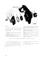
Remove
1. Place the throttle control cross shaft and fuel injection
pump linkage (A) in a soft-jawed vise.
2. Remove retaining ring (B).
3. Remove ball bearing (C) as shown in figure 6-216.
Install
1. Place the throttle control crow shaft and fuel injection
pump linkage (A) in a soft-jawed vise.
2. Install ball bearing (C) on cross shaft.
3. Install retaining ring (B).
Figure 6-215. Removing or installin g
camshaft end plate ball bearin g
retaining ring and ball bearing .
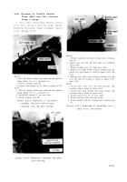
Remove
1. Remove camshaft end plate bearing inner retaining
ring (A).
2. Remove cap screw (B) and lock washer (or assembled
washer bolt).
3. Remove control lever (C) from cross shaft.
4. Remove cross shaft bracket bearing retaining ring and
bracket (D) with bearing as shown in figures 6-215 and
6-216.
5. Remove cross shaft lever bearing retaining ring and
lever (E) with two bearings as shown in figures 6-215
and 6-216.
Install
1. Install cross shaft lever (E) with bearings, and
retaining ring as shown in figure 6-215.
2. Install cross shaft bracket (D), with bearing, and
retaining ring as shown in figure 6-215.
3. Install control lever (C) on cross shaft.
4. Install cap screw (B) and lock washer.
5. Install camshaft end plate bearing inner retaining ring
(A).
Figure 6-217. Removing or installing cros s
shaft levers and bracket .
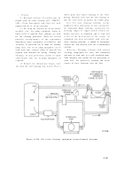
Figure 6-216. Removing camshaft end plat e
ball bearing .
6-181
Back to Top


