TM-9-2815-200-35
ENGINE, WITH CONTAINER:TURBOSUPERCHARGED, DIESEL ,FUEL INJECTION ,90-DEGREE “V” TYPE, AIR - COOLED ,12 - CYLINDER , ASSEMBLY ;MODELS AVDS-1790-2M (2815-856-4996), AVDS-1790-2A AND AVDS-1790-2AM (2815-856-9005)
TECHNICAL MANUAL; DIRECT SUPPORT, GENERAL SUPPORT AND DEPOT MAINTENANCE MANUAL INCLUDING REPAIR PARTS AND SPECIAL TOOLS LISTS
TM-9-2815-200-35 - Page 486 of 779
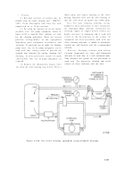
Remove
Install
1. Remove six-self-locking nuts (A) and bolts.
1. Position front cooling fan shroud rail (F) on cooling
2. Remove two cover plates (B).
fan shroud.
3. Remove eight self-locking nuts (C) and bolts.
2. Install six self-locking nuts (E) and bolts.
4. Remove rear cooling fan shroud rail (D).
3. Position rear cooling fan shroud rail (D) on fan
5. Remove six self-locking nuts (E) and bolts.
shroud.
6. Remove front cooling fan shroud rail (F).
4. Install eight self-locking nuts (C) and bolts.
5. Position two cover plates (B) on fan shroud.
6. Install six self-locking nuts (A) and bolts.
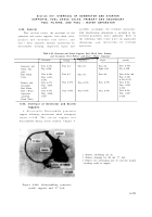
Figure 6-227. Removing or installing cooling fan shroud rails and cove r
plates .
c. Cleaning.
Refer to paragraph 6-2 .
d. Inspection and Repair.
Refer to paragraph s
6-3 and 6-4, and (1) and (2), below .
(1) In the event of complete reconditioning
of the engine and transmission shrouds, th e
rubber seals found on some shrouds must b e
removed and discarded. All paint must b e
stripped off to the bare metal before repainting .
After painting install new rubber seals o n
shrouds as required .
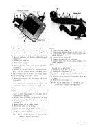
(2) Due to the high temperatures en -
countered near the turbosupercharger the lef t
inner shroud (21, fig. B-22). left outer shrou d
plate (22), turbosupercharger end shroud (24) ,
right outer plate (29), and right inner shrou d
plate (31) require painting with a high tem -
perature heat resisting paint MIL-P-14276 ,
FSN
or
equivalent.
e. Assembly.
Refer to figures 6-227 and 6-226.
Remaining shroud components not assembled a t
this point will be assembled during engin e
assembly, Chapter 7 .
6-192
Back to Top


