TM-9-2815-205-24 - Page 290 of 856
TEST AND INSPECTION
1.
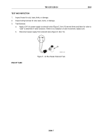
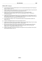
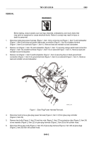
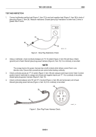
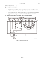
Connect multimeter positive lead (Figure 3, Item 37) to end and negative lead (Figure 3, Item 38) to body of
glow plug (Figure 3, Item 26). Measure resistance. Discard glow plug if resistance is lower than 2 ohms or
greater than 5 ohms.
+
-
00.0
37
26
38
MAINT_130
Figure 3.
Glow Plug Resistance Check.
2.
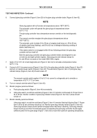
Using a multimeter, check continuity between pin “A" of socket (Figure 4, Item 39) and blue or black
(ground) end of lead. Discard glow plug power harness (Figure 4, Item 14) if no continuity is recorded.
NOTE
The orange lead on the power harness has a built-in diode which allows current flow in one
direction only. Ensure that connections are correct when testing continuity.
3.
Check continuity across pin “F" of socket (Figure 4, Item 39) and orange (crank input) end of lead. Connect
positive lead of multimeter to orange end of lead and negative lead to pin “F". If no continuity is recorded,
discard glow plug power harness (Figure 4, Item 14).
4.
Check continuity between pins “B" and “E" of socket (Figure 4, Item 39) and red (power) end of lead.
Discard glow plug power harness (Figure 4, Item 14) if no continuity is recorded.
14
39
39
MAINT_131
Figure 4.
Glow Plug Power Harness Check.
TM 9-2815-205-24
0045
0045-4
Back to Top

