TM-9-2815-205-24 - Page 296 of 856
INSTALLATION - Continued
NOTE
When connecting glow plug power harness to starter solenoid, ensure wires are connected
to correct terminals for appropriate manufacturer of starter.
11.
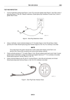
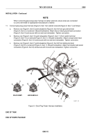
Connect glow plug power harness (Figure 8, Item 14) to starter solenoid (Figure 8, Item 1) as follows:
a.
Remove nut (Figure 8, Item 5) and lockwasher (Figure 8, Item 4) from ground terminal
(Figure 8, Item 2) on solenoid. Discard lockwasher. Attach blue or black ground lead connection
(Figure 8, Item 3) and secure with nut and new lockwasher. Tighten connection.
b.
Remove nut (Figure 8, Item 10) and lockwasher (Figure 8, Item 11) from switch terminal
(Figure 8, Item 13) on solenoid (Figure 8, Item 1). Discard lockwasher. Attach orange switch lead
connection (Figure 8, Item 12) and secure with nut and new lockwasher. Tighten connection.
c.
Remove nut (Figure 8, Item 7) and lockwasher (Figure 8, Item 8) from battery terminal
(Figure 8, Item 6) on solenoid (Figure 8, Item 1). Discard lockwasher. Attach red double lead power
connection (Figure 8, Item 9) and secure with nut and new lockwasher. Tighten connection.
1
2
3
4
5
6
7
8
9
10
11
12
14
13
13
13
6
6
2
2
DELCO-REMY
LEECE-NEVILLE
MAINT_135
Figure 8.
Glow Plug Power Harness Installation.
END OF TASK
END OF WORK PACKAGE
TM 9-2815-205-24
0045
0045-10
Back to Top


