TM-9-2815-205-24 - Page 292 of 856
TEST AND INSPECTION - Continued
6.
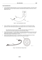
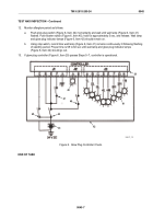
Connect glow plug controller (Figure 6, Item 29) to the glow plug controller tester (Figure 6, Item 42).
NOTE
Glow plug system will not function at temperatures above 185°F (85°C).
The automatic cycler will operate the glow plugs at temperatures below
52°F (11°C)
The glow plug controller has a temperature sensor override on the test diagnostic
pin.
The manual override energizes the glow plugs at temperatures below
185°F (85°C).
The automatic cycle includes 34 to 38 sec of preglow (wait lamp on), 58 to 62 sec
of standby (wait lamp flashing), and 58 to 62 sec of afterglow following cranking of
starter (wait lamp on).
If the starter switch is not engaged within 60 sec following preheat, the glow plug
controller will turn itself off.
Both the glow plug controller and glow plug controller tester are designed for use
on both six and eight-cylinder engines. Glow plug pins and indicator lamps for
4L and 4R are not used on the model 5063–539L engine.
7.
Apply 4.5 to 5.0 V dc to test diagnostics pin (Figure 6, Item 42) to simulate a temperature below
52°F (11°C).
8.
Connect a 24 V dc power source (Figure 6, Item 43) to the glow plug controller tester (Figure 6, Item 42)
and turn on master power switch (Figure 6, Item 40). The wait lamp (Figure 6, Item 41) and glow plug
indicator lamps (Figure 6, Item 42) should remain off.
NOTE
The manual override switch applies 4.5 to 5.0 V dc current to a diagnostic pin to simulate a
temperature of 52°F (11°C) or lower.
9.
Turn on manual override switch (Figure 6, Item 43).
10.
Monitor preglow period as follows:
a.
Push glow plug switch (Figure 6, Item 44) momentarily.
b.
Using stop watch, record time wait lamp (Figure 6, Item 41) remains continuously lit. Proper time is
34 to 38 sec. Monitor condition of glow plug indicator lamps (Figure 6, Item 42). Lamps should
remain on.
11.
Monitor standby period as follows:
Using stop watch, record time wait lamp (Figure 6, Item 41) remains flashing following Step 5. Proper
time is 58 to 62 sec and lamp should go out. Monitor glow plug indicator lamps (Figure 6, Item 42).
Glow plug indicator lamps should remain energized when wait lamp is flashing. Glow plug indicator
lamps should go out when the wait lamp goes out indicating the glow plug controller would supply
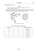
sufficient power for the glow plugs (Figure 7, Item 26) to reach their optimum operating temperature.
TM 9-2815-205-24
0045
0045-6
Back to Top

