TM-9-2815-205-24 - Page 294 of 856
INSTALLATION
1.
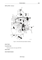
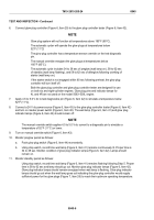
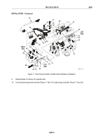
Place mounting bracket (Figure 7, Item 36) over front of air inlet housing (Figure 7, Item 20) and against
upper front cover (Figure 7, Item 21).
2.
Install two flat washers (Figure 7, Item 19), two new lockwashers (Figure 7, Item 18), and two long screws
(Figure 7, Item 17) into top of bracket and install two flat washers (Figure 7, Item 32), two new lockwashers
(Figure 7, Item 31), and two short screws (Figure 7, Item 30) into front of bracket. Torque screws
(Figure 7, Item 17) to 16–20 lb-ft (22–27 N·m) and screws (Figure 7, Item 30) to 46–50 lb-ft (62–68 N·m).
3.
Secure glow plug controller (Figure 7, Item 29) to mounting bracket (Figure 7, Item 36) with four flat washers
(Figure 7, Item 35), two new lockwashers (Figure 7, Item 16), two nuts (Figure 7, Item 33) and two short
bolts (Figure 7, Item 15). Torque screws to 13–17 lb-ft (18–23 N·m).
4.
If removed, install two clips (Figure 7, Item 24) on each side of glow plug harness (Figure 7, Item 28).
5.
Connect glow plug harness (Figure 7, Item 28) to glow plug controller (Figure 7, Item 29). Tighten securely.
6.
Apply antiseize compound to threads of three glow plugs (Figure 7, Item 26) and install glow plugs in left
cylinder head. Torque plugs to 132–156 lb-in (15–18 N·m).
NOTE
The lead locations and sides of the glow plug harness are identified by the length of the
lead. The longest lead goes on the left rear position (3L), the next longest lead goes to
2L position, and the shortest lead goes to 1L position. The same applies to the right side.
Correct installation of wires is necessary for proper diagnostics to aid in locating a failed
glow plug.
7.
Install three ends (Figure 7, Item 25) of glow plug harness (Figure 7, Item 28) to corresponding glow plug
(Figure 7, Item 26) locations in left cylinder head.
8.
Secure glow plug harness (Figure 7, Item 28) to two brackets (Figure 7, Item 22) on left cylinder head with
two bolts (Figure 7, Item 23) and two nuts (Figure 7, Item 27). Torque bolts to 30–35 lb-ft (41–47 N·m).
TM 9-2815-205-24
0045
0045-8
Back to Top

