TM-9-2815-205-24 - Page 302 of 856
INSTALLATION
1.
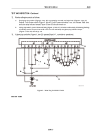
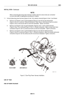
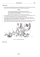
For all models except model 5063-539L, position new gasket (Figure 4, Item 1) and new preformed packing
(Figure 4, Item 6) on air box heater (Figure 4, Item 5). Lubricate packing with engine oil.
NOTE
For all except model 5063-539L, do not install the bolt, in lower left hole
(when facing engine), and copper flat washer, fastening air box heater assembly to
front cover, until connection of ground wire.
Model 5063-539L has a special air heater hole plug and no air box heater.
2.
For model 5063-539L, position new gasket (Figure 4, Item 1) and new preformed packing (Figure 4, Item 6)
on air box heater hole plug (Figure 4, Item 5). Lubricate packing with engine oil.
3.
For all models except model 5063-539L, install air box heater (Figure 4, Item 5), two new copper flat
washers (Figure 4, Item 4), and two bolts (Figure 4, Item 3) in engine front cover (Figure 4, Item 2) with fuel
inlet port positioned at bottom. Torque bolts to 13–17 lb-ft (18–23 N·m).
4.
For model 5063-539L, install air heater hole plug (Figure 4, Item 5), and three new flange head locking bolts
(Figure 4, Item 3) in engine front cover (Figure 4, Item 2). Torque bolts to 13–17 lb-ft (18–23 N·m).
3
4
5
6
1
2
MAINT_139
Figure 4.
Air Box Heater Installation.
END OF TASK
TM 9-2815-205-24
0046
0046-6
Back to Top

