TM-9-2815-205-24 - Page 308 of 856
INSPECTION-ACCEPTANCE AND REJECTION CRITERIA - Continued
NOTE
On model 5063-5299, the thermostat valve should start opening at 162–167°F
(72–75°C). Valve should be fully open at 182°F (83°C).
On model 5063-5392, thermostat valve should start opening at 177–182°F
(81–83°C). Valve should be fully open at 197°F (92°C).
b.
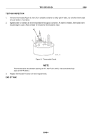
Agitate water to maintain an even temperature throughout container. As water is heated, thermostat
valve should begin to open. Allow at least 10 minutes for thermostat to react.
c.
Replace thermostat not meeting this requirement.
END OF TASK
INSTALLATION
1.
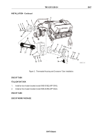
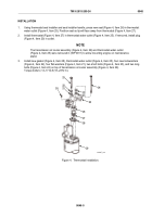
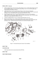
Install new gasket (Figure 3, Item 6), left coolant outlet elbow (Figure 3, Item 19), two flat washers
(Figure 3, Item 16), two new lockwashers (Figure 3, Item 17), and two screws (Figure 3, Item 18) on front of
left cylinder head. Torque screws to 30–35 lb-ft (41–47 N·m).
2.
For models 5063-5299 and 5063-5392, if removed, install two plugs (Figure 3, Item 23) in side of left coolant
outlet elbow (Figure 3, Item 19).
3.
Using seal installer and handle, press new seal (Figure 3, Item 9) in thermostat housing cover
(Figure 3, Item 15). Position seal (Figure 3, Item 9) with lip facing toward inside of thermostat housing
cover (Figure 3, Item 15).
4.
Install thermostat (Figure 3, Item 8) into thermostat housing cover (Figure 3, Item 15).
5.
Install new gasket (Figure 3, Item 7), thermostat housing cover (Figure 3, Item 15), four flat washers
(Figure 3, Item 11), four new lockwashers (Figure 3, Item 12), and four screws (Figure 3, Item 13) on left
coolant outlet elbow (Figure 3, Item 19). Torque screws to 30–35 lb-ft (41–47 N·m).
6.
For models 5063-5299 and 5063-5392, if removed, install plug (Figure 3, Item 10) in top of thermostat
housing cover (Figure 3, Item 15).
7.
Install drain cock (Figure 3, Item 14) in bottom of thermostat housing cover (Figure 3, Item 15).
8.
Install new gasket (Figure 3, Item 5), right coolant outlet elbow (Figure 3, Item 4), two flat washers
(Figure 3, Item 3), two new lockwashers (Figure 3, Item 2), and two screws (Figure 3, Item 1) on front of
cylinder head. Torque screws to 30–35 lb-ft (41–47 N·m).
9.
If removed, install plug (Figure 3, Item 24) in right coolant outlet elbow (Figure 3, Item 4).
10.
Install crossover tube (Figure 3, Item 21), two hoses (Figure 3, Item 22), and four clamps (Figure 3, Item 20)
between coolant outlet elbow (Figure 3, Item 4) and coolant outlet elbow (Figure 3, Item 19). Tighten
hose clamps.
TM 9-2815-205-24
0047
0047-4
Back to Top

