TM-9-2815-205-24 - Page 315 of 856
INSTALLATION
1.
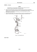
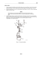
Using thermostat seal installer and seal installer handle, press new seal (Figure 4, Item 26) in thermostat
water outlet (Figure 4, Item 25). Position seal so lip will face away from thermostat (Figure 4, Item 27).
2.
Install thermostat (Figure 4, Item 27) in thermostat water outlet (Figure 4, Item 25). If removed, install plug
(Figure 4, Item 20) in outlet.
NOTE
The transmission oil cooler assembly (Figure 4, Item 29) and thermostat water outlet
(Figure 4, Item 25) were removed in (WP 0011) to allow mounting engine on maintenance
stand.
3.
Install new gasket (Figure 4, Item 28), thermostat water outlet (Figure 4, Item 25), four new lockwashers
(Figure 4, Item 22), four flat washers (Figure 4, Item 21), two short bolts (Figure 4, Item 23), and two long
bolts (Figure 4, Item 24) on top of transmission oil cooler assembly (Figure 4, Item 29).
Torque bolts to 13–17 lb-ft (18–23 N·m).
20
21
22
23
24
22
21
25
26
27
28
29
MAINT_146
Figure 4.
Thermostat Installation.
TM 9-2815-205-24
0048
0048-5
Back to Top

