TM-9-2815-205-24 - Page 319 of 856
REMOVAL - Continued
2.
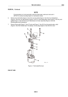
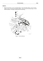
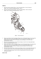
Disconnect fuel inlet hose assembly (Figure 2, Item 5) from tee (Figure 2, Item 10) at rear of left cylinder
head and from elbow (Figure 1, Item 9) at front of right cylinder head. Remove hose assembly.
5
10
MAINT_149
Figure 2.
Fuel Line Removal/Installation.
3.
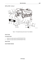
Loosen nuts on two elbows (Figure 1, Item 7) at front of cylinder heads and remove fuel crossover tube
(Figure 1, Item 8).
END OF TASK
INSTALLATION
1.
Insert fuel crossover tube (Figure 1, Item 8) into two elbows (Figure 1, Item 7) at front of cylinder heads.
Tighten nut on each elbow.
2.
Connect fuel inlet hose assembly (Figure 2, Item 5) to elbow (Figure 1, Item 9) at front of right cylinder head
and to tee (Figure 2, Item 10) at rear of left cylinder head. Tighten hose connections.
3.
If removed, install clip (Figure 1, Item 4) on fuel inlet hose assembly (Figure 1, Item 5).
4.
Install clip (Figure 1, Item 4), located on fuel inlet hose assembly (Figure 1, Item 5), flat washer
(Figure 1, Item 3), new lockwasher (Figure 1, Item 2), and screw (Figure 1, Item 1) on air inlet housing
(Figure 1, Item 6). Torque screw to 16–20 lb-ft (22–27 N·m).
END OF TASK
FOLLOW ON TASK
1.
Install coolant crossover tube (WP 0047).
2.
Install air pump support (WP 0042).
END OF TASK
END OF WORK PACKAGE
TM 9-2815-205-24
0049
0049-3/blank
Back to Top

